Our Products
Contact Information
Longxi Industrial Park, Taizhou, Jiangsu, China
Tel: 86-523-86600162
Fax: 86-523-86600162

Gantry Machining Center - HG2016
Model: HG2016
Category: Machine Tools / Machining Centers / Vertical Machining Centers, Double-Column-Type
Characteristics
Gantry Machining Center – HG2016 (or gantry milling machine, gantry mill, GMC ) is a distinctive machine tool with its double-column structure. The gantry refers to the CNC router that hangs over the worktable to perform machining processes. It is the rapid movement of the gantry that makes this machine extra efficient.
HG Machinetools’ Gantry Machining Centeris composed of a worktable, a gantry, a ram, a tool magazine, an accessory head library, and a CNC system. It is mainly suitable for processing large and complex shaped workpieces, including fixed beam type (fixed crossbeam, worktable movement or rotation), movable beam type (moving crossbeam up and down, worktable front and back movement), movable column type (fixed workbench, gantry frame movement), and overhead crane type (fixed workbench, moving crossbeam)
A. Advantages of HG Machinetools’ Gantry Machining Center – HG2016
The spindle of the our Gantry Machining Center adopts the high precision spindle assembly, the belt type milling head, the spindleis the servo motor drive. X, y, Z axis servo control, the direct connect architecture, with automatic lubricating system, machine tools to achieve a rapid motion; X, y, Z three directions to feed with high accuracy high strength ball screw, high feed speed; driving motor through flexible coupling with screw direct coupled, servo servo motor directly deliver power to the high precision ball screw, no backlash to ensure the positioning precision of the machine tool.
The spindleof Taiwan Brandwith high speed and high precision, high rigidity spindle unit, axial and radial load capacity, speed up to 6000rpm; the center of spindle blowing structure, with rapidly in the tool release after cleaning of the spindle cone center of high pressure gas, to ensure the accuracy of tool clamping;
X, y, Z axis servo control, direct coupled structure is adopted in the Taiwan high precision and high intensity of ball screw, screw installation of pre stretching, connecting rigidity, high feed speed; the servo motor directly transferring power to a high precision ball screw, no backlash, ensure the machine tool positioning accuracy. The Z shaft is provided with a hydraulic balancing device, which ensures.
X/Y/Z three direction guide rails, the lead screw all uses the airtight protection, guarantees the lead screw and the guide rail clean, guarantees the machine tool transmission and the movement precision;
The outer protection of the machine tool is designed with the ring structure, which is safe and reliable;
Machining center configuration: the high quality Tool Magazine, the shortest path tool change, tool change accurately, short time, high efficiency, the test run, in line with the reliability requirements;
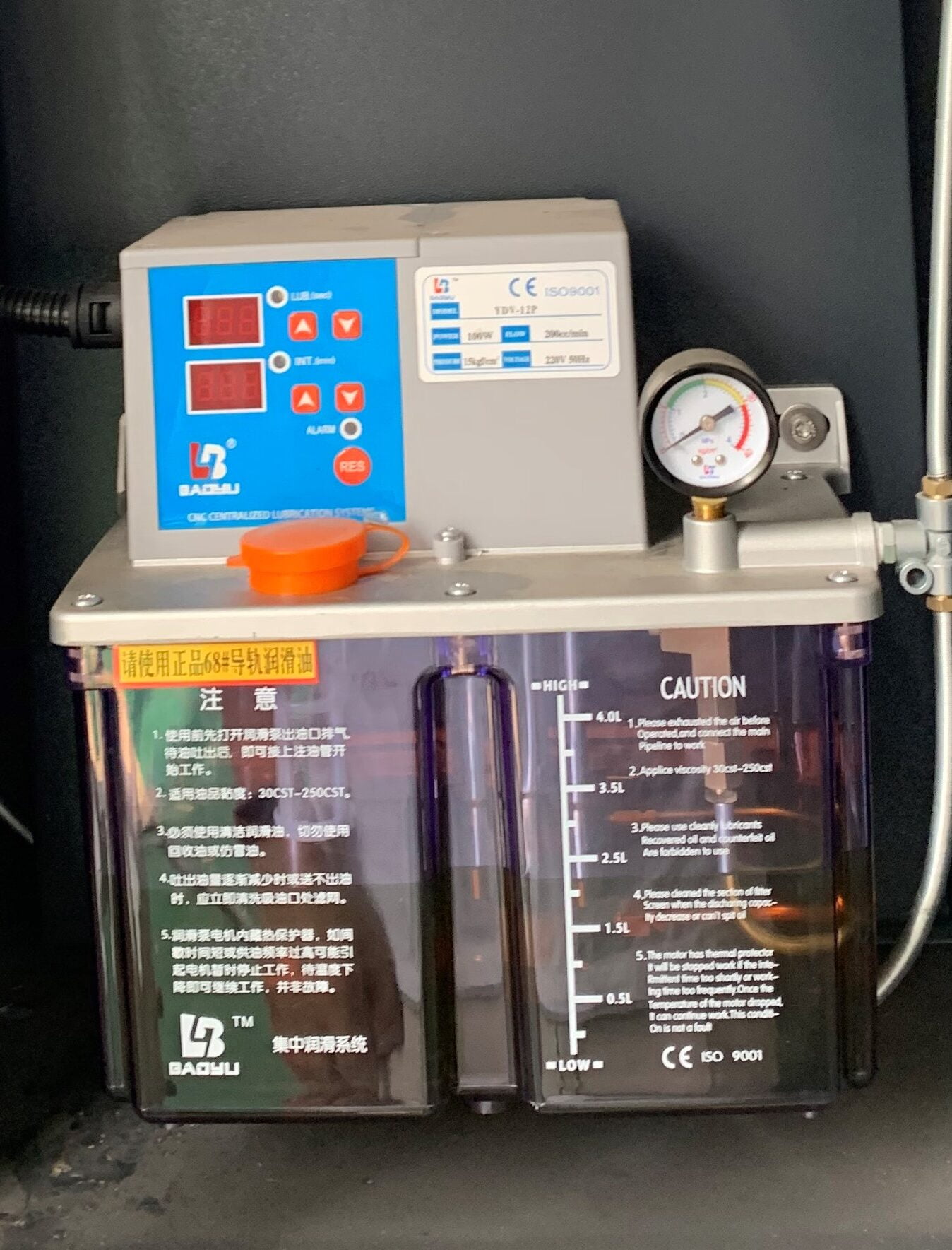
Using the centralized automatic lubrication device, timing, quantitative automatic intermittent lubrication, stable and reliable work;
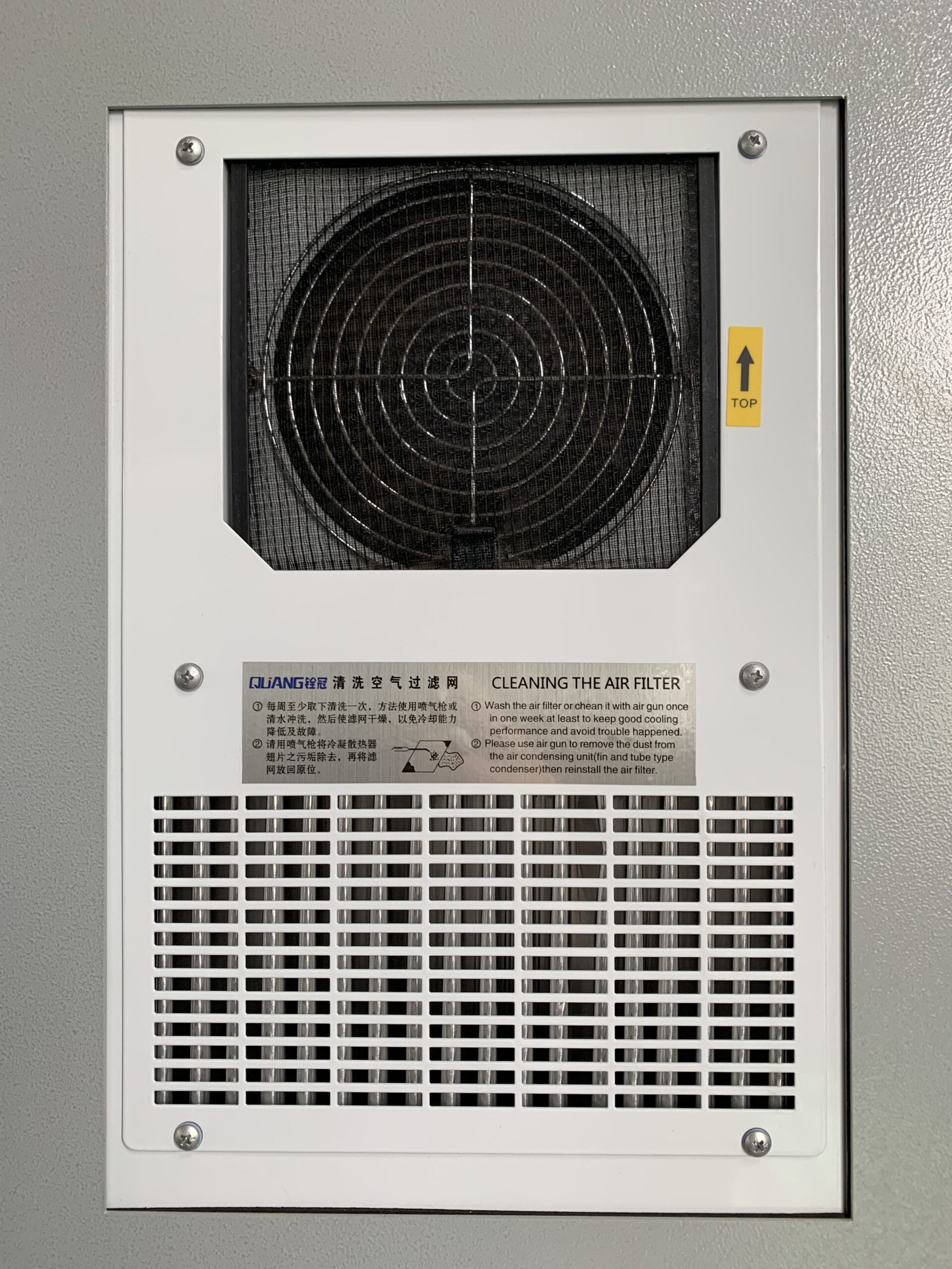
The machine electrical system wiring neatly, the structure is reasonable, the electric box seal is good, is equipped with the heat exchange system, guaranteed the good use environment;
CNC system (FANUC, Mitsubishi, Siemens, wide number) can be selected. The system has perfect and reliable interlocking, safety protection and fault diagnosis and alarm functions, equipped with RS232 communication interface;
The operation of HG Machinetools’Gantry Machining Center would beeasy, flexible and quick.
B. Key Features of HG Machinetools’ Gantry Machining Center – HG2016
a. Environmentally friendly Cover
b. Controller Integrated
c. Servo Motors
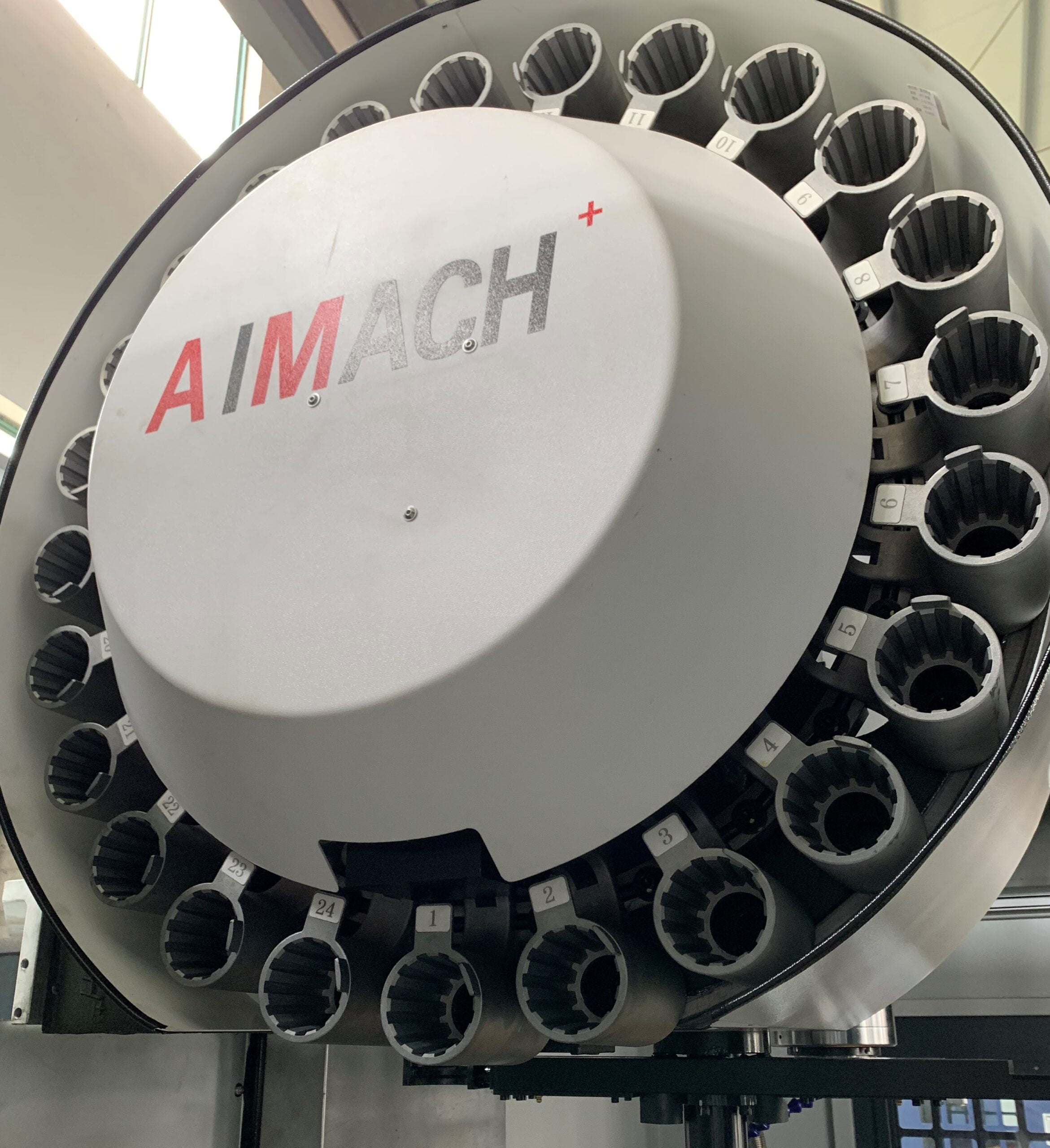
d. Tool Magazine
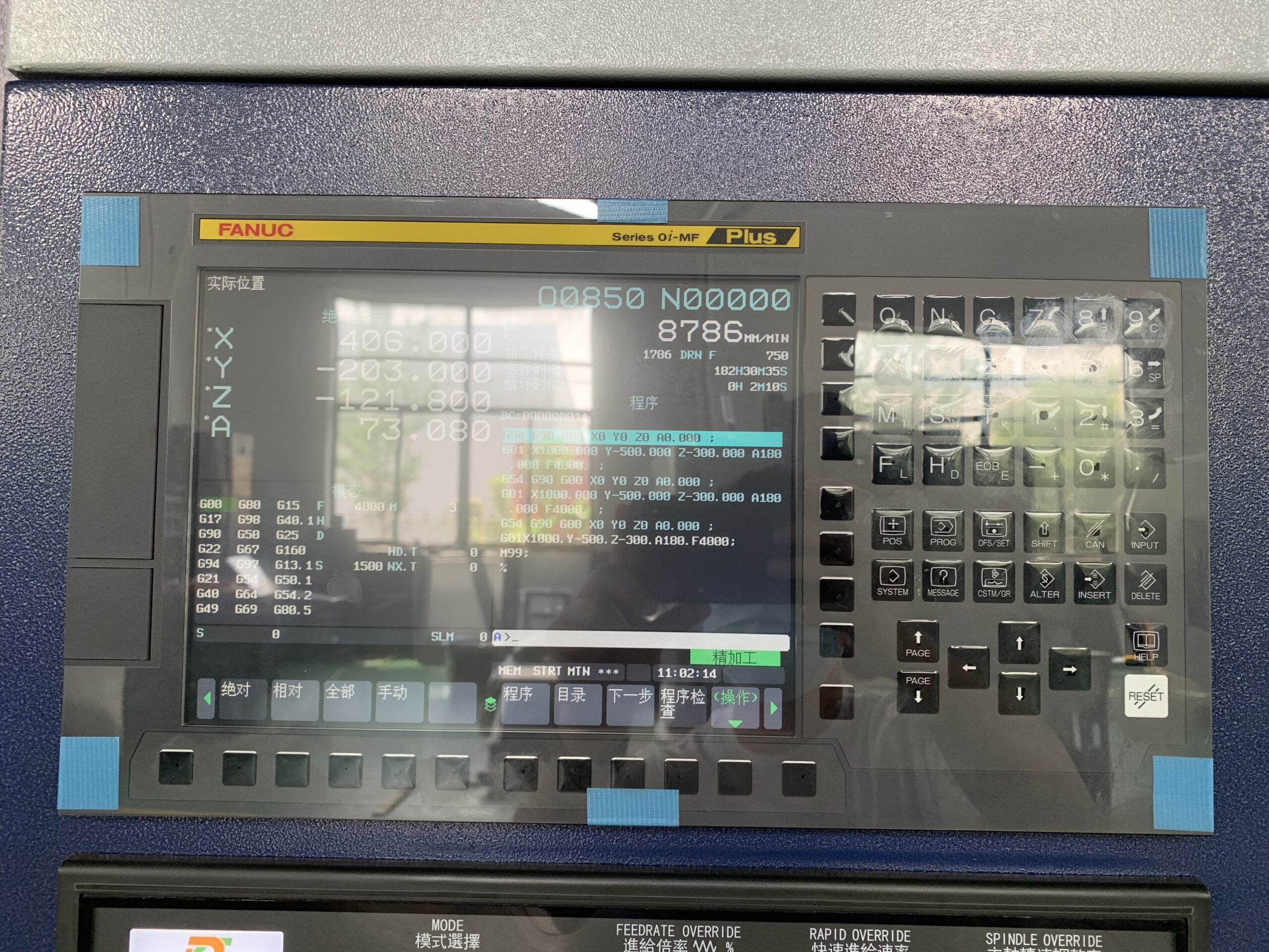
e. With FANUC control system
f. Automatic Lubrication System
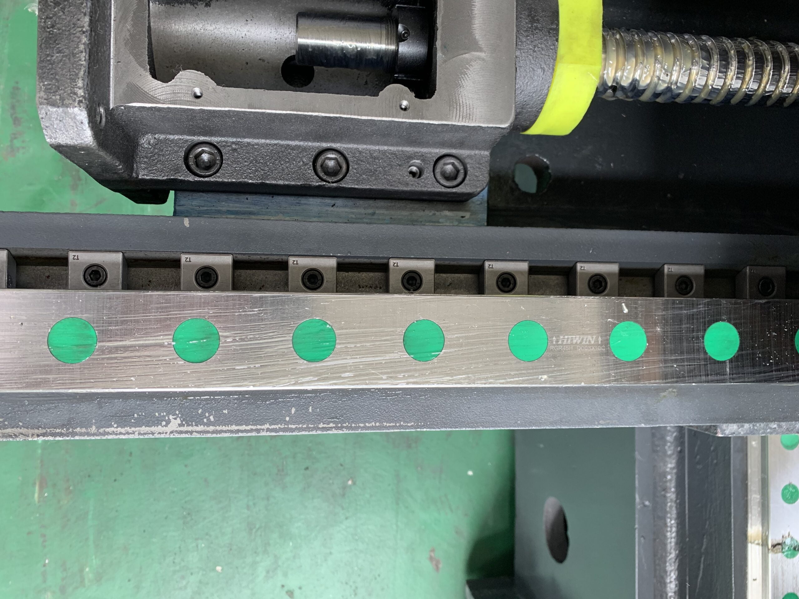
g. HIWIN/PMI Roller Type Linear Guideway
h. HIWIN/PMI Ball Screw
i. FAG Bears
j. Tool Magazine OKADA/Aimach
C. Application of HG Machinetools’ Gantry Machining Center – HG2016
Gantry Machining Center – HG2016 is used in CNC milling, boring, drilling, tapping, processing of steel, cast steel, cast iron etc.. Machine tool accessory head to realize the of all kinds of plate, plate, shell and mould for complex parts in a fixture in complete drilling, milling, boring, reaming, reaming, tapping a variety of processes. It can be used for small batch spare parts, processing and manufacturing, of complex, high precision parts processing more show its superiority, also can compose the automatic production line for mass production, to ensure the parts of product quality and efficient production.
D. Optional
1. Different Control System Optional
2. 4th-Axis / 5th-Axis Optional
3. Different Speed of Spindle Optional
4. Different Type of Tool Magazine Optional
5. Tools Capacity of Tool Magazine Optional
Specifications
Pls do not hesitate to contact us if you need any help with your next machining centers!

CNC Control System
Fanuc(Japan), Mitsubishi (Japan), Syntec (Taiwan,China) Optional
- Adopting high-performance and highly reliable high-speed microprocessing systems;
- Dynamic simulation of tool path, intelligent warning display, self diagnosis and other features;
- Multi segment pre reading control is particularly suitable for high-speed and large-scale program processing;
- RS-232 serial transmission, memory card transmission, USB transmission, combined with DNC standard processing configuration, facilitates the transmission of large capacity programs and online processing, with better processing efficiency and effectiveness
Spindle From Taiwan, China
Speed 6000/8000/10000/12000 RPM Optional
Spindle and motor belt are designed with a 1:1 connection, and the main motor is a low inertia motor with a speed of 10000rpm. It is a wise choice for high-precision, high rigidity, and heavy cutting situations; If there are higher requirements for surface smoothness, a 12000 rpm direct spindle can also be selected.


Cooling System
HG Machine is equipped with a cooling system, and the combination of a large flow pump and many nozzles can solve the machining problems of tool overheating and workpiece deformation due to machining heat.
Some Components of Our Machines
| ITEM | HG-2016 | HG-2518 | HG-3220 | HG-5022 | HG-6025 | HG-8032 |
|---|
| Working Table Size(W x L)mm | 1400×2100 | 1600×2700 | 1800×3000 | 2000×5000 | 2300×6000 | 2500×8000 |
| Tabel Travel(X Axis) mm | 2000 | 2500 | 3200 | 5000 | 6000 | 8000 |
| Spindle Slide Travel (Y Axis) mm | 1700(Tool change stroke 1780) |
1900(Tool change stroke 2000) |
2000 | 2200(Auxiliary stroke 2700) |
2700(Auxiliary stroke 3050) |
3200(Auxiliary stroke 3800) |
| Spindle Up & Down Travel (Z Axis) mm | 800 | 800 | 1000 | 1000 | 1000 | 1250 |
| Gantry Width mm | 1700 | 1900 | 2000 | 2300 | 2700 | 3200 |
| Gantry Height mm | 1080 | 1080 | 1300 | 1400 | 1400 | 1730 |
| Distance From Spindle nose to worktable mm | 200~1000 | 200~1000 | 180~1180 | 280~1280 | 280~1280 | 300~1550(Optional Increased Height for Column by 300,500mm , & new hight would be 600~1850;800~2050) |
| T-Slot QTY-Distance*Width | 7-22×200 | 9-22×180 | 9-22×190 | 9-28×200 | 11-28×200 | Center 11-28×200 Both Sides 1-28×180 |
| Max Loading Weight Ton | 4 | 5.5 | 5 | 14 | 18 | 30 |
| Spindle Taper & Size | BT50/φ190 | BT50/φ190 | BT50-φ190 | BT50/φ200 | BT50/φ200 | BT50/φ200 |
| Spindle Transmission Type - Belt | Speed 6000r/min | Speed 6000r/min | Speed 8000r/min / Pulley transmission ratio Standard 1.5:1 ;Optional 1:1 |
Speed 6000r/min | Speed 6000r/min | Speed 6000r/min |
| Pulley transmission ratio Standard 1.5:1 ;Optional 1:1 | Pulley transmission ratio Standard 1.5:1 ;Optional 1:1 | Speed 6000r/min Pulley transmission ratio Standard 4:1 |
Pulley transmission ratio Standard 1.5:1 ;Optional 1:1 | Pulley transmission ratio Standard 1.5:1 ;Optional 1:1 | Pulley transmission ratio Standard 4:1 | |
| - ZF Speed Reduction + Belt (Optional) | Speed 6000r/min Pulley transmission ratio Standard 4:1 | Speed 6000r/min Pulley transmission ratio Standard 4:1 | Speed 12000r/min | Speed 6000r/min Pulley transmission ratio Standard 4:1 | Speed 6000r/min Pulley transmission ratio Standard 4:1 | Speed 6000r/min Pulley transmission ratio Standard 1.5:1 |
| - Gear Head(Wemas) | Max. Speed 6000r/min Pulley transmission ratio Standard 4.4:1 |
Max. Speed 6000r/min Pulley transmission ratio Standard 4.4:1 |
Speed 6000r/min Pulley transmission ratio Standard 4.4:1 | Speed 6000r/min Pulley transmission ratio Standard 4.4:1 | Speed 6000r/min Pulley transmission ratio Standard 4.4:1 | |
| Rapid Feeding Speed(m/min) | 15 | 15 | 15 | 12 | 10 | 8 |
| Cutting Feeding Speed(m/min) | 10 | 10 | 10 | 8 | 6 | 5 |
| Spec of Ball Screw for X/Y/Z | X:5010、Y:5010、Z:5010 | X:6312、Y:5010、Z:5010 | X:8020、Y:5010、Z:5010 | X:8020、Y:6312、 Z:5010 |
X:10020、Y:6316、 Z:5010 |
X:10020(Movable nut) Y:8020、Z:6316 |
| Spec of Guideway for X/Y/Z | X:Roller Type Linear Guideway 55/6 Y:Roller Type Linear Guideway 55/4 Z:Rectangular Linear Guideway |
X:Roller Type Linear Guideway 55/8 Y:Roller Type Linear Guideway 55/4 Z:Rectangular Linear Guideway |
X:Roller Type Linear Guideway 55 Y:Roller Type Linear Guideway 45 (55Optional) Z:Rectangular Linear Guideway |
X:Roller Type Linear Guideway 55/14 Y:Roller Type Linear Guideway 55/4 Z:Rectangular Linear Guideway |
X:Roller Type Linear Guideway 55/18 Y:Roller Type Linear Guideway 55/4 Z:Rectangular Linear Guideway |
X:4 x Roller Type Linear Guideway 55/36 Y:2 x Roller Type Linear Guideway 55/8 Z:Rectangular Linear Guideway |
| Transmission Type for X/Y/Z | X/Y/Z Direct Connect | X/Y/Z Direct Connect | X/Y/Z Direct Connect | X Belt Drive 2.5:1 Y direct transmission 1:1 Z direct transmission 1:1 |
X Planet Gear Transmission 4:1;Y Planet Gear Transmission 3:1; Z direct transmission 1:1(Optional : X Belt Drive 2.5:1, Y Direct Transmission 1:1; Z Direct transmission 1:1 |
X Planet Gear Transmission 3:1+ Belt 2.5:1 Y Planet Gear Transmission 4:1 Z Planet Gear Transmission 3:1(Optional : Z Belt Drive 2:1) |
| Recommended For Spindle motor | According to the Control System | According to the Control System | According to the Control System | 22kW Wide Area Motors | 22kW Wide Area Motors | 30kW Wide Area Motors |
| Recommended For Servo Motors | According to the Control System | According to the Control System | According to the Control System | X:50N·m;Y:40N·m; Z:30N·m(Contacting Break) |
X:50N·m;Y:40N·m; Z:30N·m(Contacting Break) |
X:60N·m;Y:40N·m; Z:40N·m(Contacting Break) |
| Control System | Fanuc / Syntec / Mitsubishi Optional | Fanuc / Syntec / Mitsubishi Optional | Fanuc / Syntec / Mitsubishi Optional | Fanuc / Syntec / Mitsubishi Optional | Fanuc / Syntec / Mitsubishi Optional | Fanuc / Syntec / Mitsubishi Optional |
| Tool Magazine | Optional | Optional | Optional | Optional | Optional | Optional |
| Machine Floor Space (LxWxH) | 5600×3300×3295 | 6840×3600×3295 | 8000×3710×3800 | 11750×4740×4100 | 13750×5140×4100 | 19240×6670×5470 |
| Machine Weight | 16 | 18.5 | 22 | 38 | 50 | 92 |
|---|
Featured products


